Login
Login Register
 Steel Construction Published the List of Highly Influential Articles of 2020


The steel-framed structure of the One Vanderbilt building was designed by structural firm Severud Partners Consulting and utilises a total of 26,000t of steel. A key feature of the building is the full floor-to-ceiling windows, ranging in height from 14 ft.6in. (4.42m) to 24 ft. (7.32m), most of which are column-free floor spaces with unrivalled 360° views. The core is a hybrid system of steel frames and high-strength concrete shear walls, an approach that allowed the project's construction manager, Iron Lions Gate, a division of AECOM Construction, to better control the project schedule. A 9ft. (2.74m) thick concrete raft foundation was installed in the lower portion of the tower, and the tower's core was reinforced with cantilevered steel trusses at three intermediate levels, which were closely coordinated with the MEP design consultant to minimise disruption to the state-of-the-art building's MEP systems.
In addition, a steel Tuned Mass Damper (TMD) was installed to keep the acceleration of the building within a comfortable range for the building occupants. Column transition systems on the 5th and 13th floors of the tower give the building its distinctive shape and require a full floor high truss structure. By using steel structural members, the structural engineers were able to minimise potential disturbances caused by chords and internal diagonal bars. At the truss nodes, cast nodes were used to ensure that the joints were as dense as possible, while allowing for smooth force transfer and simplified site construction. The cast nodes are both isotropic and weldable. In fact, when two or more trusses meet at the core, no other connection is more practical than a cast steel node. The efficiency and economy of wide flange sections made them the first choice for the main body of the building frame, but box section columns and welded steel plate beams were used where their loads exceeded the capacity of the rolled members. The combination of different thicknesses and widths of steel plates, together with the stability of the welded detailing, allowed the project team to design a section form that could fulfil any geometric constraints.
At the top of the building, where the "crown" and "ventilator" elements define the upper end of the rectangular conical spire, the hollow steel tube section is ideal for supporting the various complex details of the glass façade, with its high bending capacity - even at large height-to-width ratios - and its high bending capacity - the "crown" and "ventilator" elements define the upper end of the rectangular conical spire. Its high bending capacity - even at high aspect ratios and long unsupported lengths - and its adaptability to factory-welded connection nodes simplify the processing of steel elements. In addition, end-plate bolted joints, which can be used at the construction site for horizontal and diagonal member connections, greatly facilitate the erection process.
Located at the top of the building on top of the "ventilation pipe" is a 128 ft. (39.01 m) high spire, also made of steel plates. The spire was machined into transportable sections that can be joined together by flanges and easily bolted together at a height of 1,401 ft. (427.02m). Glass was considered for the inner panels, but it could not resist the heat generated by the nearby flue. A separate wind tunnel test study was conducted to determine the wind loads on the spire section and the interaction between the spire and the building frame. As a result, diagonal stiffening ribs were installed on each side of the spire to interfere with the wind field and help control icing. As an added benefit, these stiffening ribs continue the special effect of directing the view all the way to the top of the building.
The tower utilises a steel-first erection sequence advocated by Severud Partners Consulting. The columns, beams, and diagonal bracing located at the core are designed to be self-supporting structures that can reach up to 12 stories. As the steel erection progressed, construction of reinforced concrete shear walls began below. Using a self-erecting formwork system within the core and hand-held formwork externally, the concrete work proceeded upwards along with the steel structure, typically maintaining a six-storey gap to the upper floors. This method of construction allowed the project construction manager, Iron Lionsgate, a subsidiary of AECOM Construction, to mitigate potential delays due to concrete pouring, while maximising the impact of faster erection times on the overall schedule.
The core shear wall - the main structural component of the lateral resistance system - is 30in. (76mm) thick and has a compressive strength of up to 14,000psi (96.53MPa), with Grade 80 steel used throughout. Controlling lateral displacement and vibration was particularly important to maintain performance in this supertall building, so cantilevered steel trusses were used to stiffen the concrete shear walls at the three intermediate equipment floors.
Due to vertical space constraints, the building was designed as a complex system with two steel masses: one suspended from above and the other supported on the ground, which are interconnected to extend the range of vibration frequencies. After the installation of the column transition system on the 5th and 12th floors of the building, optoelectronic targeting devices were installed at key points in the frame. As construction progressed, these phototargets could be monitored from within the Chrysler Building and other nearby high-rise buildings to confirm the building's performance and inform the installation team farther away from the building if, for example, additional shims were needed for column splicing.
Advanced APD Method
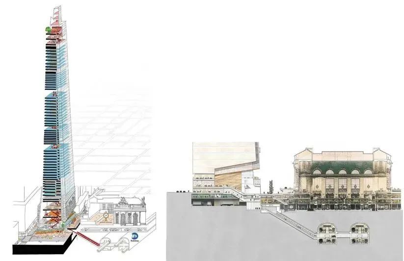
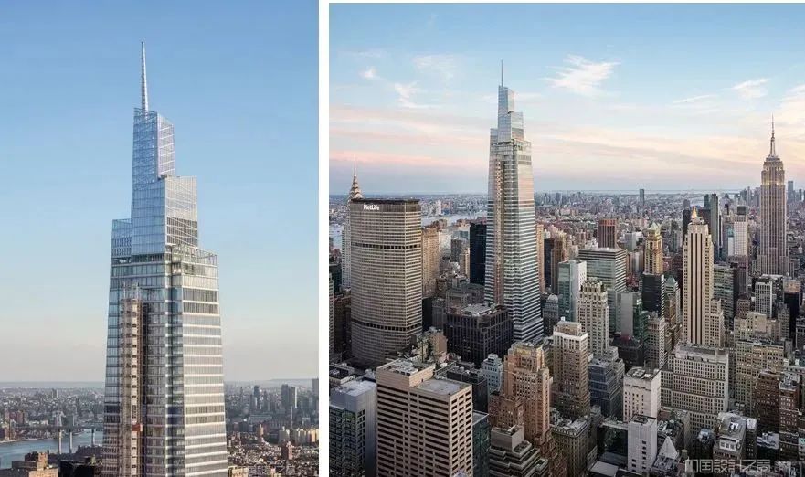
How to build one of the tallest buildings in the United States in a densely populated, bustling area near one of the world's busiest transport hubs? And within an accelerated schedule? First, the design and modelling of the steel connection nodes had to start as early as possible. Located between 42nd and 43rd Streets, along Madison and Vanderbilt Avenues, and just outside New York's Grand Central Terminal, the One Vanderbilt building is the second-tallest and newest office building in New York City, and a vital part of the transit hub sequence. The 77-storey, 1,401 ft. (427.02 m) tall, 1.7 million ft.2 (157,900 m²) building, which was reconstructed from the demolition of the original building, broke ground in 2016 and is now completed ahead of schedule and within budget.
One Vanderbilt's designer, KPF (Kohn Pedersen Fox) Architects, is familiar to us as a firm specialising in the design of skyscrapers around the globe, and is currently responsible for 4 of the 10 tallest buildings in the world.KPF Architects designed One Vanderbilt to consist of KPF Architects designed One Vanderbilt, which consists of four interlocking wedges spiralling upwards. The building's structural design, by Severud Partners Consulting and Engineering, features steel framing, diagonal columns, transition structures, and an outrigger truss surrounding a concrete core, with the construction sequence beginning with the installation of the steel framing using a temporary steel core, which will ultimately be permanently embedded in the concrete core. This approach allows the project to be constructed as if there were no concrete core, taking full advantage of the speed of steel erection and thus reducing the overall construction period.
The building's projected occupancy date is the end of 2020, with work to install the superstructure, which uses more than 25,000t of steel, beginning in the summer of 2017. Given that the project went through several design iterations in the autumn of 2015 and winter of 2016, the project drew on Thornton Tomasetti's construction engineering practices to take advantage of the fast-track construction benefits of steel to shorten the duration and ensure that the project was completed on schedule.Thornton Tomasetti's Advanced Project Delivery APD ( Thornton Tomasetti's Advanced Project Delivery (APD) methodology, together with the company's structural engineering expertise, provided early design of steel connections and Tekla modelling services, allowing for early factory orders and steel detailing.
Throughout the project, Thornton Tomasetti worked closely with the design and construction teams to bridge the gap between design and construction, starting work 15 months before the structural steel elements arrived on site. At this early stage, the company developed a complex connection node concept for review and approval by Severud Partners Consulting Engineers, and used the Tekla model to identify and resolve much of the missing geometric information and frame-to-frame collisions in the early available files, as well as to obtain the final force information for the connection node design.Thornton Tomasetti and Severud Partners Consulting Engineers worked closely with the design and construction teams to bridge the gap between design and construction, 15 months before the steel members arrived on site. An internal request for information between Tomasetti and Severud Partners Consulting and Engineering, with the former frequently suggesting design changes or waiving specified force requirements in specific cases, has helped to improve the design, detailing, fabrication and erection of the steel connection nodes.
This early information on steel connections and geometries was able to be sent to the structural steel tenderers in the summer of 2016. To further enhance the understanding of the project requirements, Tekla models and diagrams of the connection configurations were also given to illustrate some of the more complex areas, and to help the steelwork tenderers suggest some of the improvements in fabrication and erection. With the completion of the podium modelling, further detailing and Tekla progress models were sent to the tenderers as part of the tender process. Early design of the connections confirmed the need for solid cast steel nodes to enable transfer of forces in both directions. These cast steel units ranged in weight from 3 to 22t, with the largest cast steel node being approximately 3ft. x 3ft. x 10ft. (0.91m x 0.91m x 3.05m). These special conditions for the three nodes in the lower part of the building were detailed and also included in the tender documents, allowing the steel bidders to have a better understanding of what was required early on in the project, leading to more accurate and reliable bids. Finally in October 2016, Banker Steel Structures Ltd was awarded the steel fabrication contract for the project.
The project was split into 7 processes for detailing. Each process had a pre-scheduled ABM (Advanced Bill of Materials) date for materials and a RFD (Released for Detailing) date for the detailing. Process 1 is the bottom of the podium, from the foundation to the 6th floor. This process consisted of a number of 24 ft. (7.32 m) high transition trusses consisting of welded box sections and 9 ft. (2.74 m) high steel plate girders, as well as horizontal bracing for a number of floors, and a sloped suspended ceiling above the lobby. The majority of the transition truss connection nodes are 26in. (0.66m) wide welded nodes machined from multi-layer steel plates up to 6in. (15mm) thick. Process 2 is the upper portion of the podium, from the 6th to the 13th floor, and includes another set of conversion structures. Processes 3 to 6 include 45 typical office floors, and include 3 arm extension reinforcement layers. The highlight of process 7 is the roof structure enclosed by glazing, with side columns made of exposed hollow steel tube section HSS, horizontal members and diagonal braces of size HSS 22 x 22. Following the signing of the steel fabrication contract, an ABM model of the bill of materials for Processes 1 and 2 with a total weight of 11,500t (45% of the total steel consumption of the project) was submitted to the steel processor Banker Steel Structures Ltd. together with the anchors and pre-built steel plates for the detailed construction. Three weeks later, the RFD model for Process 1 with a total weight of 7,000t was submitted for detailing. This was clearly one of the most complex processes of the project, and the steel detailing and fabrication process was carried out ahead of schedule.
As the design and modelling of the connection nodes progressed, any valuable information required between Thornton Tomasetti and the design team, together with the status of the connection design and Tekla modelling, was reported to the entire project team at weekly project meetings. The Sequential Model Delivery Plan included in the contract with Banker Steel Structures Ltd enabled the entire project team, both designers and owners, to provide solutions and make critical decisions in a timely manner. This approach not only helped to streamline the information flow, but also helped to identify potential collisions at an early stage, ensuring that the project schedule could be fast-tracked.
The RFD model for Process 2 was produced a month and a half after Process 1, and a number of steel components, as well as a large quantity of structural steel, had already been converted into shop drawings for review and approval. The RFD models for the subsequent processes, which were also given essentially at two-month intervals, allowed the steel to be ordered in actual lengths rather than the typical ABM order lengths, where the design of the connection nodes is still unknown, thus avoiding material wastage. Structural components with long lead times are ordered earlier based on available time length information. Confirmation of the connection design and modelling information before the order is placed allows the dimensions of the elements to be modified in advance, which is particularly beneficial when simplifying the connection design or eliminating the need for costly reinforcement, e.g. by increasing the wall thicknesses of hollow steel tube sections where the connection nodes are partially undersized for out-of-plane stresses.
Because the steel frame structure was constructed before the concrete structure, Thornton Tomasetti also co-ordinated the relationship between the reinforcing steel in the reinforced concrete structure and any main steel connections, including pre-welding rebar joints in the connecting material or leaving holes in the site where the rebar could pass through. These practices help to minimise site handover issues between the steel and concrete trades and provide greater flexibility. The steel construction drawings were reviewed by Thornton Tomasetti and the design team to ensure that they were completed in accordance with the detailing in the model, and additionally based on the appropriate connection forces. Any comments that might affect the design of the connections were evaluated and coordinated before the shop drawings were sent to the construction team. The construction drawing submission review process went very smoothly, especially for a project of this size and complexity, and most of the drawings were reviewed and approved after the first submission. The steel structure for this project was installed beginning in the summer of 2017, with construction drawings submitted up to the 31st floor and reviewed and approved up to the 27th floor. As the design progressed, the fabrication and erection period for the steelwork was shortened by at least 8 months in preparation of the Tekla connection models. Connection node design and modelling work was largely completed in November 2017 All steel construction drawings were substantially submitted in late spring 2018, and the steel frame structure was completed in mid-September 2019 with the installation of the last member of the spire, with the ribbon-cutting ceremony taking place a year later. As they say, "the early bird catches the worm", and in the case of One Vanderbilt, the early design and modelling of the steel connection nodes enabled the opening of Manhattan's newest signature supertall building ahead of schedule, even in the midst of a global epidemic.
Note: Portions of this article were translated from the American Institute of Steel Construction's Modern Steel Construction magazine, Issue 3, 2021.
Client: SL Green Real Estate/Hines/Korea National Pension Corporation
Construction Management: AECOM Tishman
Architectural Design: KPF (Kohn Pedersen Fox) Architects
Structural Design: Severud Partners Consulting Engineers
Nodal design and modelling: Thornton Tomasetti
Structural Steel Fabrication: Banker Steel Structures, LLC, Lynchburg, Virginia
Structural Steel Erection: NYC Construction Company, New York, NY
Structural Steel Detailing: Banker Steel Structures, LLC, Lynchburg, VA
Cast Steel Fabrication: Ellwood Speciality Steel, Inc.
This article was translated from Modern Steel Construction magazine, American Institute of Steel Construction, Issue 5, 2022.